Magnetic field through a coil. Not all turns are shown.
A coil with $N$ turns and radius $r$ is inside a magnetic field $\vec B$.
Given:
$B = |\vec B| = ~b~ T$.
$N = ~N~$.
$r = ~r~ cm$.
Find the magnitude of the total magnetic flux $|\Phi|$ through the coil.
Very big or very small numbers can be entered as "1.234e-6" (for $ 1.234\times 10^{-6}$).
if (int_count_times_randomized == 0){
return 10.00;
} else {
return random_min_max_precision(2, 15, 0); //defined in setup_exercise_all.js
}
if (int_count_times_randomized == 0){
return 100;
} else {
return random_min_max_precision(100, 2000, -2); //defined in setup_exercise_all.js
}
if (int_count_times_randomized == 0){
return 0.5;
} else {
return random_min_max_precision(0.1, 2.5, 1); //defined in setup_exercise_all.js
}
Hint:
$|\Phi| = N B A$ for $\vec B$ entering perpendiculary into the plane of a coil.
Make sure $A$ is expressed in $m^2$ before using the above equation.
Solution
We first calculate the area in $m^2$ using $r = ~r~ cm = [[return (~r~*1e-2)]] m$:
$$
A = \pi r^2
= \pi ([[return (~r~*1e-2)]] m)^2
= [[return namespace_em_induction.get_scientific_notation_latex(namespace_em_induction.area, 2)]] m^2
$$
The magnitude of the magnetic flux is:
$$
\begin{eqnarray}
|\Phi| &=& N B A
= (~N~) (~b~ T)([[return namespace_em_induction.get_scientific_notation_latex(namespace_em_induction.area, 2)]] m^2)\\
&=& [[return namespace_em_induction.get_scientific_notation_latex(namespace_em_induction.flux, 2)]] Wb
\end{eqnarray}
$$
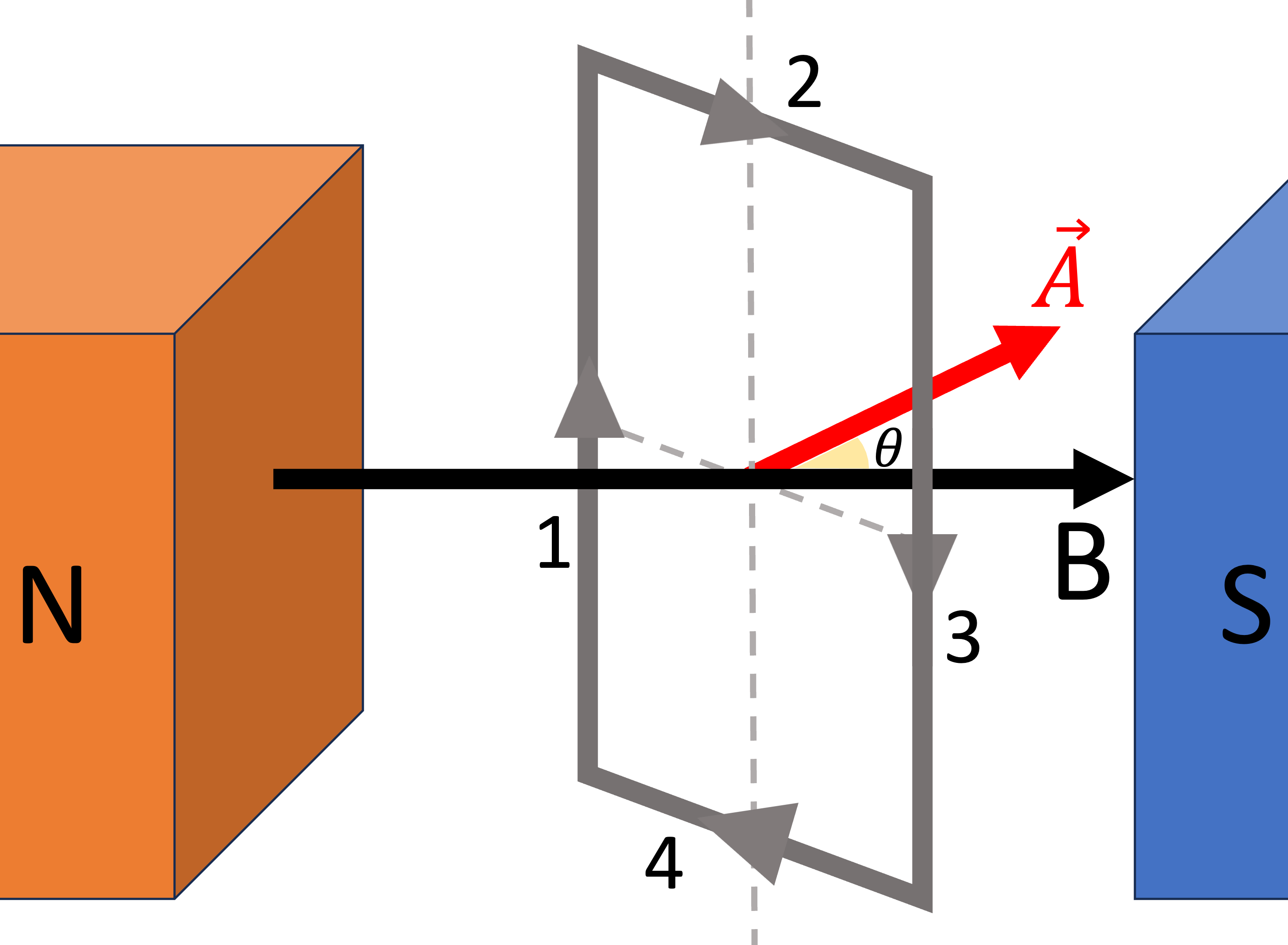
Magnetic field through a coil at an angle. Not all turns are shown.
A coil with $N$ turns and radius $r$ is inside a magnetic field $\vec B$.
Given:
$B = |\vec B| = ~b~ T$.
$N = ~N~$.
$r = ~r~ cm$.
Find the magnitude of the total magnetic flux $|\Phi|$ through the coil.
Very big or very small numbers can be entered as "1.234e-6" (for $ 1.234\times 10^{-6}$).
if (int_count_times_randomized == 0){
return 10.00;
} else {
return random_min_max_precision(2, 15, 0); //defined in setup_exercise_all.js
}
if (int_count_times_randomized == 0){
return 5;
} else {
return random_min_max_precision(100, 2000, -2); //defined in setup_exercise_all.js
}
if (int_count_times_randomized == 0){
return 0.5;
} else {
return random_min_max_precision(0.1, 2.5, 1); //defined in setup_exercise_all.js
}
if (int_count_times_randomized == 0){
return -30;
} else {
return random_min_max_precision(-80, 90, 0, true); //defined in setup_exercise_all.js
}
Hint:
$\vec A$ is always perpendicular to the plain of the coil, so in this problem $\vec A$ is vertical.
$\Phi = N B A \cos(\theta)$, where $\theta$ is the angle between $\vec B$ and $\vec A$.
Make sure $A$ is expressed in $m^2$ before using the above equation.
Solution
The angle between the area vector $\vec A$ and $\vec B$.
We first calculate the area in $m^2$ using $r = ~r~ cm = [[return (~r~*1e-2)]] m$:
$$
A = \pi r^2
= \pi ([[return (~r~*1e-2)]] m)^2
= [[return namespace_em_induction.get_scientific_notation_latex(namespace_em_induction.area, 2)]] m^2
$$
The area vector $\vec A$ is always perpendicular to the plain of the coil, so in this problem $\vec A$ is vertical. We will choose $\vec A$ to point vertically up (choosing $\vec A$ to point vertically down will only flips the sign of $\Phi$, but the question only ask for the magnitude of the flux).
The angle between $\vec B$ and $\vec A$ is:
[[
if (~theta_b~>0){
return `$$ \\theta = ${~theta_b~ + 90}^\\circ - 90^\\circ = ${Math.abs(~theta_b~)}^\\circ $$`;
} else {
return `$$ \\theta = 90^\\circ - ${~theta_b~ + 90}^\\circ = ${Math.abs(~theta_b~)}^\\circ $$`;
}
]]
The magnitude of the magnetic flux is:
$$
\begin{eqnarray}
|\Phi| &=& N B A \cos (\theta)
= (~N~) (~b~ T)([[return namespace_em_induction.get_scientific_notation_latex(namespace_em_induction.area, 2)]] m^2)(\cos ([[return Math.abs(~theta_b~)]]^\circ)) \\
&=& [[return namespace_em_induction.get_scientific_notation_latex(namespace_em_induction.flux, 2)]] Wb
\end{eqnarray}
$$
Exercise - Faraday's law of electromagnetic induction
if (int_count_times_randomized == 0){
return 10.00;
} else {
return random_min_max_precision(2, 15, 0); //defined in setup_exercise_all.js
}
if (int_count_times_randomized == 0){
return 100;
} else {
return random_min_max_precision(100, 2000, -2); //defined in setup_exercise_all.js
}
if (int_count_times_randomized == 0){
return 1.2;
} else {
let b = random_min_max_precision(-2.5, 2.5, 1);
while (Math.abs(b)<0.2) { //>
b = random_min_max_precision(-2.5, 2.5, 1);
}
return b;
}
if (int_count_times_randomized == 0){
return 2;
} else {
let b = random_min_max_precision(-2.5, 2.5, 1);
while (Math.abs(b)<0.2) { //>
b = random_min_max_precision(-2.5, 2.5, 1);
}
return b;
}
if (int_count_times_randomized == 0){
return 0.2;
} else {
return random_min_max_precision(0.1, 5.0, 1); //defined in setup_exercise_all.js
}
return Math.abs(~b_f~ - ~b_i~)>0.2;
Initial magnetic field.Final magnetic field.
A coil with $N$ turns and radius $r$ is inside a magnetic field $\vec B$ changing uniformly during the time period $\Delta t$. Take the area vector $\vec A$ to point vertically upward.
Given:
We first calculate the area in $m^2$ using $r = ~r~ cm = [[return (~r~*1e-2)]] m$:
$$
A = \pi r^2
= \pi ([[return (~r~*1e-2)]] m)^2
= [[return namespace_em_induction.get_scientific_notation_latex(namespace_em_induction.area, 2)]] m^2
$$
The angle between $\vec A$ and $\vec B_{initial}$ is $[[return namespace_em_induction.theta_i]] ^\circ$. The initial the magnetic flux is:
$$
\begin{eqnarray}
\Phi_{initial} &=& N B A \cos \theta_{initial}
= (~N~) ([[return Math.abs(~b_i~)]] T)([[return namespace_em_induction.get_scientific_notation_latex(namespace_em_induction.area, 2)]] m^2) (\cos([[return namespace_em_induction.theta_i]] ^\circ)) \\
&=& [[return namespace_em_induction.get_scientific_notation_latex(namespace_em_induction.flux_i, 2)]] Wb
\end{eqnarray}
$$
The angle between $\vec A$ and $\vec B_{final}$ is $[[return namespace_em_induction.theta_f]] ^\circ$. The final the magnetic flux is:
$$
\begin{eqnarray}
\Phi_{final} &=& N B A \cos \theta_{final}
= (~N~) ([[return Math.abs(~b_f~)]] T)([[return namespace_em_induction.get_scientific_notation_latex(namespace_em_induction.area, 2)]] m^2) (\cos([[return namespace_em_induction.theta_f]] ^\circ)) \\
&=& [[return namespace_em_induction.get_scientific_notation_latex(namespace_em_induction.flux_f, 2)]] Wb
\end{eqnarray}
$$
The change in the magnetic flux is:
$$
\begin{eqnarray}
\Delta \Phi &=& \Phi_{final} - \Phi_{initial}
= [[return namespace_em_induction.get_scientific_notation_latex(namespace_em_induction.flux_f, 2)]] Wb - ([[return namespace_em_induction.get_scientific_notation_latex(namespace_em_induction.flux_i, 2)]]Wb) \\
&=& [[return namespace_em_induction.get_scientific_notation_latex(namespace_em_induction.delta_flux, 2)]] Wb
\end{eqnarray}
$$
Applying Faraday's Law:
$$
\begin{eqnarray}
\mathcal{E} &=& -\frac{d\Phi}{dt} = -\frac{\Delta \Phi}{\Delta t} \\
&=& -\frac{[[return namespace_em_induction.get_scientific_notation_latex(namespace_em_induction.delta_flux, 2)]] Wb}{~t~ s} \\
&=& [[return namespace_em_induction.get_scientific_notation_latex(namespace_em_induction.emf, 2)]] V
\end{eqnarray}
$$
The direction of the emf can be found using the right hand grip rule. Point your thumb along $\vec A$, then your four fingers wraps along the positive direction for $\mathcal{E}$.
If $\mathcal{E} \gt 0$: emf is along the four fingers, counterclockwise in this problem.
If $\mathcal{E} \lt 0$: emf is opposite to the four fingers, clockwise in this problem.
Magnet moving [[return (namespace_em_induction.boolean_magnet_closer)? "toward":"away from"]] a coil.
A magnet is moving [[return (namespace_em_induction.boolean_magnet_closer)? "toward":"away from"]] a coil.
Find the direction of the induced emf in the coil when viewed above.
In a test you must show your reasonings to receive credits for this problem.
Magnet moving [[return (namespace_em_induction.boolean_magnet_closer)? "toward":"away from"]] a coil.
A magnet is moving [[return (namespace_em_induction.boolean_magnet_closer)? "toward":"away from"]] a coil.
Find the direction of the induced emf in the coil when viewed from the left.
In a test you must show your reasonings to receive credits for this problem.
Magnet moving [[return (namespace_em_induction.boolean_magnet_closer)? "toward":"away from"]] a coil.
A magnet is moving [[return (namespace_em_induction.boolean_magnet_closer)? "toward":"away from"]] a solenoid connected to a resistor.
Find the direction of the induced current flowing through the resistor.
Very big or very small numbers can be entered as "1.234e-6" (for $ 1.234\times 10^{-6}$).
Hint:
Work out the following step by step for a single loop:
Direction of $\vec B_{ext}$ produced by the magnet through the coil.
Change in the magnetic field strength (increasing or decreasing?).
Direction of the induced field $\vec B_{induced}$ that opposes the change above.
Use right hand grip rule to determine the direction of $\mathcal{E}$ to produce $\vec B_{induced}$.
Follow the current in the solenoid as deduced to the resistor.
Solution
$\vec B_{ext}$ produced by the magnet for a single loop.The induced magnetic field $\vec B_{induced}$ produced by the induced current to oppose the change in flux.For the current to flow through the solenoid in the [[return (namespace_em_induction.boolean_emf_induced_ccw)? "counterclockwise":"clockwise"]] direction, the current must pass the resistor to the [[return (namespace_em_induction.boolean_current_to_right)? "right":"left"]].
Lenz's law states that the induced emf due to a change in a magnetic flux is directed to oppose the change.
First consider only a single loop.
Step
Answer
Explanation
Direction of $\vec B_{ext}$
[[return (~b_i~>0)?"left":"right"]]
$\vec B_{ext}$ determined solely by the orientation of the magnet
The switch on the electromagnet about to [[return (namespace_em_induction.boolean_magnet_closer)? "close":"open"]].
The switch on the electromagnet about to [[return (namespace_em_induction.boolean_magnet_closer)? "close":"open"]].
Find the direction of the induced current flowing through the resistor when the switch is flipped.
Very big or very small numbers can be entered as "1.234e-6" (for $ 1.234\times 10^{-6}$).
Hint:
Work out the following step by step for a single loop:
Direction of $\vec B_{ext}$ produced by the electromagnet through the coil.
Change in the magnetic field strength (increasing or decreasing?).
Direction of the induced field $\vec B_{induced}$ that opposes the change above.
Use right hand grip rule to determine the direction of $\mathcal{E}$ to produce $\vec B_{induced}$.
Follow the current in the solenoid as deduced to the resistor.
Solution
$\vec B_{ext}$ produced by the electromagnet when the switch is closed, at the location of the coil.The induced magnetic field $\vec B_{induced}$ produced by the induced current to oppose the change in flux.For the current to flow through the solenoid in the [[return (namespace_em_induction.boolean_emf_induced_ccw)? "counterclockwise":"clockwise"]] direction, the current must pass the resistor to the [[return (namespace_em_induction.boolean_current_to_right)? "right":"left"]].
Lenz's law states that the induced emf due to a change in a magnetic flux is directed to oppose the change.
First consider only a single loop.
Step
Answer
Explanation
Direction of $\vec B_{ext}$
[[return (~b_i~>0)?"left":"right"]]
$\vec B_{ext}$ determined solely by the orientation of the magnet
Exercise - Electric field of electromagnetic induction
if (int_count_times_randomized == 0){
return 3;
} else {
return random_min_max_precision(-10, 10, 1, false, -2.1, 2.1); //defined in setup_exercise_all.js
}
if (int_count_times_randomized == 0){
return 0.7;
} else {
return random_min_max_precision(-2, 2, 1, false, -0.3, 0.3); //defined in setup_exercise_all.js
}
if (int_count_times_randomized == 0){
return 0.2;
} else {
return random_min_max_precision(0.1, 2, 1); //defined in setup_exercise_all.js
}
if (int_count_times_randomized == 0){
return 7;
} else {
return random_min_max_precision(1, 10, 0); //defined in setup_exercise_all.js
}
return (true);
A ring inside a magnetic field (in red) in the beginning.
A metallic ring with radius $r = ~r~cm$ is placed inside a magnetic field with magnitude $[[return Math.abs(~b_i~)]] T$ pointing [[return (~b_i~>0)? "out of":"into"]] the screen. The magnitude of the field [[return (~b_i~ * ~b_delta~>0)? "increases":"decreases"]] by $[[return Math.abs(~b_delta~)]] T$ in $~t~ s$. Assume the area vector points in the positive $z$-direction, i.e. out of the screen in the calculations below.
Find:
The initial magnetic flux in the ring.
The final flux in the ring.
The change in magnetic flux.
The induced emf $\mathcal{E}$ (keep the sign according to Faraday's law).
The magnitude of the E field (positive number only).
The direction of the E field.
Very big or very small numbers can be entered as "1.234e-6" (for $ 1.234\times 10^{-6}$).
Hint:
$$
\begin{eqnarray}
\Phi_B &=& BA \\
\mathcal{E} &=& -\frac{d\Phi_B}{dt} \\
E &=& \frac{1}{2\pi r}\mathcal{E}
\end{eqnarray}
$$
The right hand grib rule when applied to an area vector pointing out the screen means:
$\mathcal{E}\gt 0$: counterclockwise.
$\mathcal{E}\lt 0$: clockwise.
According to our calculations above, $\mathcal{E}$ is [[return (namespace_em_induction.emf>0)?"greater":"less"]] than zero, it means the emf and the E field must point in the [[return (namespace_em_induction.emf>0)?"counterclockwise":"clockwise"]] direction.
First we find the area of the capacitor plate:
$$
\begin{eqnarray}
A_{plate} &=& \pi R^2 \\
&=& \pi (~r_capacitor~ \times 0.01 m )^2 \\
&=& [[return sf_latex(namespace_em_induction.area_capacitor)]] m^2
\end{eqnarray}
$$
For comparison, the area of the Amperian loop is:
$$
\begin{eqnarray}
A_{loop} &=& \pi r^2 \\
&=& \pi (~r_loop~ \times 0.01 m )^2 \\
&=& [[return sf_latex(namespace_em_induction.area_loop)]] m^2
\end{eqnarray}
$$
The charge density on the plate is:
$$
\begin{eqnarray}
\sigma &=& \frac{q}{A_{plate}} \\
&=& \frac{~q~ \times 10^{-9} C}{[[return sf_latex(namespace_em_induction.area_capacitor)]] m^2} \\
&=& [[return sf_latex(namespace_em_induction.charge_density)]] C/m^2
\end{eqnarray}
$$
The E field:
$$
\begin{eqnarray}
E &=& \frac{\sigma}{\epsilon_0} \\
&=& \frac{[[return sf_latex(namespace_em_induction.charge_density)]] C/m^2}{8.854 \times 10^{-12}F/m} \\
&=& [[return sf_latex(namespace_em_induction.e_field)]] V/m
\end{eqnarray}
$$
Cross-sectional view.
Since $r\geq R$, all the field inside the capacitor is captured by the Amperian loop:
$$
\begin{eqnarray}
\Phi_E &=& E (\pi R^2) \\
&=& E A_{plate} \\
&=& ([[return sf_latex(namespace_em_induction.e_field)]] V/m)([[return sf_latex(namespace_em_induction.area_capacitor)]] m^2) \\
&=& [[return sf_latex(namespace_em_induction.flux)]] Vm
\end{eqnarray}
$$
For the displacement current:
$$
\begin{eqnarray}
\Phi_E &=& E (\pi R^2) & \text{ note that it is $R$, not $r$!} \\
&=& (\frac{\sigma}{\epsilon_0}) (\pi R^2) & \text{ because $E=\frac{\sigma}{\epsilon_0}$}\\
&=& (\frac{q}{\epsilon_0 \pi R^2}) (\pi R^2) & \text{ because $\sigma=\frac{q}{\pi R^2}$}\\
&=& \frac{q}{\epsilon_0} \\
\Rightarrow I_D &=& \epsilon_0 \frac{d\Phi_E}{dt} \\
&=& \frac{dq}{dt} \\
&=& I \\
&=& ~i~ A
\end{eqnarray}
$$
Since $r\lt R$, only the field inside the loop is captured by the Amperian loop. The area of the loop is:
$$
\begin{eqnarray}
\Phi_E &=& E (\pi r^2) \\
&=& E A_{loop} \\
&=& ([[return sf_latex(namespace_em_induction.e_field)]] V/m)([[return sf_latex(namespace_em_induction.area_loop)]] m^2) \\
&=& [[return sf_latex(namespace_em_induction.flux)]] Vm
\end{eqnarray}
$$
For the displacement current:
$$
\begin{eqnarray}
\Phi_E &=& E (\pi r^2) & \text{ note that it is $r$, not $R$.} \\
&=& (\frac{\sigma}{\epsilon_0}) (\pi r^2) & \text{ because $E=\frac{\sigma}{\epsilon_0}$}\\
&=& (\frac{q}{\epsilon_0 \pi R^2}) (\pi r^2) & \text{ because $\sigma=\frac{q}{\pi R^2}$, not $\sigma=\frac{q}{\pi r^2}$!}\\
&=& \frac{q}{\epsilon_0} \frac{r^2}{R^2} \\
\Rightarrow I_D &=& \epsilon_0 \frac{d\Phi_E}{dt} \\
&=& \frac{dq}{dt}\frac{r^2}{R^2} \\
&=& I \frac{r^2}{R^2}\\
&=& (~i~ A) \frac{(~r_loop~ cm)^2}{(~r_capacitor~ cm)^2}\\
&=& (~i~ A) ([[return sf_latex(namespace_em_induction.factor_radius)]]) \\
&=& [[return sf_latex(namespace_em_induction.current_displacement)]] A
\end{eqnarray}
$$
$I_C=0A$ because no charges are flowing pass the loop, so $I_{enclosed} = I_D = [[return sf_latex(namespace_em_induction.current_displacement)]] A$.
Applying Ampere-Maxwell law gives:
$$
\begin{eqnarray}
2\pi r B &=& \mu_0I_{enclosed} \\
\Rightarrow B &=& \frac{\mu_0 I_{enclosed}}{2\pi r} \\
&=& \frac{(4\pi \times 10^{-7} H/m) ([[return sf_latex(namespace_em_induction.current_displacement)]] A)}{2\pi (~r_loop~ \times 0.01m)} \\
&=& [[return sf_latex(namespace_em_induction.b_field)]] T
\end{eqnarray}
$$
Amperian loop in a circular capacitor.
For comparison, the magnetic field around the wire left of the plate (where $I_C = I$, $I_D = 0$) is:
$$
\begin{eqnarray}
B_{wire} &=& \frac{\mu_0 I}{2\pi r} \\
&=& \frac{(4\pi \times 10^{-7} H/m) (~i~ A)}{2\pi (~r_loop~ \times 0.01m)} \\
&=& [[return sf_latex(namespace_em_induction.b_field_wire)]] T
\end{eqnarray}
$$
Exercise - A bar on a rail inside a magnetic field
if (int_count_times_randomized == 0){
return 3;
} else {
return random_min_max_precision(-10, 10, 0, false, -0.5, 0.5); //defined in setup_exercise_all.js
}
if (int_count_times_randomized == 0){
return 5;
} else {
return random_min_max_precision(-10, 10, 0, false, -0.5, 0.5); //defined in setup_exercise_all.js
}
if (int_count_times_randomized == 0){
return 2;
} else {
return random_min_max_precision(1, 5, 0, false); //defined in setup_exercise_all.js
}
if (int_count_times_randomized == 0){
return 6;
} else {
return random_min_max_precision(1, 10, 0, false); //defined in setup_exercise_all.js
}
return (true);
A bar gliding on a rail inside a magnetic field.
A bar with length $l=~l~ m$ and resistance $R= ~r~ \Omega$ is rolling on a metal rail (with negligible resistance) to the [[return (~v~>0)?"right":"left"]] at $[[return Math.abs(~v~)]] m/s$. There is a magnetic field with magnitude $B=[[return Math.abs(~b~)]] T$ in the background.
Find:
The emf induced. Take the area vector of the loop to be pointing out of the screen, so enter a positive value for a counterclockwise emf, negative for clockwise.
The magnitude of the current flowing in the bar.
The direction of the current flowing in the bar.
For magnitude of the magnetic force acting on the bar.
The green circle represents the direction of the emf, the red arrow is the current, and the thin black arrow is the force. Note that the force is always against the motion of the bar.
For the figure we can see the field is pointing [[return (~b~ > 0)? "out of":"into"]] the screen. Defining the $z$-direction to be pointing out the screen, we have $B_z = ~b~ T$.
Faraday's law of electromagnetic induction:
$$
\begin{eqnarray}
\mathcal{E} &=& - \frac{d\Phi_B}{dt} \\
&=& - \frac{d(B_z A)}{dt} \\
&=& - B_z \frac{dA}{dt} & \text{magnetic field is constant but area changes}
\end{eqnarray}
$$
The area inside the loop is $A = l x$, therefore:
$$
\begin{eqnarray}
\frac{dA}{dt} &=& \frac{d (lx)}{dt} \\
&=& l\frac{dx}{dt} \\
&=& l v \\
&=& (~l~ m) ( ~v~ m/s) \\
&=& [[return sf_latex(namespace_em_induction.da_by_dt)]] m^2/s
\end{eqnarray}
$$
By Ohm's law, the magnitude of the current:
$$
\begin{eqnarray}
I &=& \frac{V}{R} \\
&=& \frac{|\mathcal{E}|}{R} \\
&=& \frac{[[return sf_latex(Math.abs(namespace_em_induction.emf))]] V}{~r~ \Omega} \\
&=& [[return sf_latex(Math.abs(namespace_em_induction.current))]] A
\end{eqnarray}
$$
The direction of $\mathcal{E}$ earlier gives the direction of the current.
The magnitude of the force:
$$
\begin{eqnarray}
F &=& |I \vec L \times \vec B| \\
&=& |([[return sf_latex(Math.abs(namespace_em_induction.current))]] A) (~l~ m) ([[return Math.abs(~b~)]] T)| \\
&=& [[return sf_latex(Math.abs(namespace_em_induction.force))]] N
\end{eqnarray}
$$
The direction of the force can be found with the right hand rule for cross product. However, by Lenz's law, we know that the force is always opposite to the change, so it must point opposite to the direction of the velocity $
\vec v$. Since $\vec v$ points [[return (~v~>0)? "right":"left"]], $\vec F$ must points [[return (~v~>0)? "left":"right"]].
$\mathcal{E}= $
return sf_math(namespace_em_induction.emf)
5%
$V$ (positive value for counterclockwise, negative for clockwise) $I= $
if (int_count_times_randomized == 0){
return 3;
} else {
return random_min_max_precision(-10, 10, 0, false, -1, 1); //defined in setup_exercise_all.js
}
if (int_count_times_randomized == 0){
return 5;
} else {
return random_min_max_precision(-10, 10, 0, false, -1, 1); //defined in setup_exercise_all.js
}
if (int_count_times_randomized == 0){
return 2;
} else {
return random_min_max_precision(1, 5, 0, false); //defined in setup_exercise_all.js
}
if (int_count_times_randomized == 0){
return 6;
} else {
return random_min_max_precision(-10, 10, 0, false, -1, 1); //defined in setup_exercise_all.js
}
return (true);
A bar moving in a magnetic field.
A bar with length $l=~l~ m$ is moving to the [[return (~v~>0)?"right":"left"]] at $[[return Math.abs(~v~)]] m/s$. There is a magnetic field with magnitude $B=[[return Math.abs(~b~)]] T$ in the background. A charge $q = ~q~ C$ is moving along with the bar. From the point of view of the charge on the bar, the magnetic field appears as an electric field ("the effective electric field") $E_{eff}$.
Find:
The magnitude of the magnetic force on the charge $q$.
The direction of the magnetic force.
The magnitude of the effective electric field in the bar.
The direction of the effective electric field in the bar.
The magnitude of the potential difference produced by the effective electric field.
The magnitude of the electric force on the charge $q$ produced by the effective electric field.
Suppose you want to impose an additional electric field $E_{opposite}$ on the bar so the charge $q$ experience no net force. What should the direction of $E_{opposite}$ be?
Magnitude of the magnetic force on the charge:
$$
\begin{eqnarray}
F_B = |q \vec v \times \vec B| \\
&=& ([[return Math.abs(~q~)]] C) ([[return Math.abs(~v~)]]m/s) ([[return Math.abs(~b~)]] T) \\
&=& [[return sf_latex(Math.abs(namespace_em_induction.force))]]N
\end{eqnarray}
$$
The force points [[return (namespace_em_induction.force>0)? "up":"down"]], as can be seen by applying the right hand rule.
From the point of view of a charge on the bar, the magnetic force can be interpreted as an electric force:
$\vec F_B = q \vec v \times \vec B \equiv q \vec E_{eff}$. This gives:
$$
\begin{eqnarray}
\vec E_{eff} &=& \vec v \times \vec B \\
\Rightarrow E_{eff} &=& |\vec v \times \vec B| & \text{ writing $E_{eff} = |\vec E_{eff}|$} \\
&=& ([[return Math.abs(~v~)]]m/s) ([[return Math.abs(~b~)]] T) \\
&=& [[return sf_latex(Math.abs(namespace_em_induction.e_field))]] V/m
\end{eqnarray}
$$
The effective E field points [[return (namespace_em_induction.e_field>0)? "up":"down"]], as can be seen by applying the right hand rule.
Remember $E_y = -\frac{dV}{dy} \Rightarrow dV = -E_y dy$.
The magnitude of the potential difference is:
$$
\begin{eqnarray}
|\Delta V| &=& E_{eff} |\Delta y| \\
&=& (E_{eff}) (l)\\
&=& ([[return sf_latex(Math.abs(namespace_em_induction.e_field))]] V/m) (~l~ m) \\
&=& [[return sf_latex(Math.abs(namespace_em_induction.emf))]] V
\end{eqnarray}
$$
This potential difference is in fact the same as the emf $\mathcal{E} = -\frac{d\Phi_B}{dt}$ we computed in the earlier problem. This is just an alternative way of understanding it.
The electric force produced by $E_{eff}$ is:
$$
\begin{eqnarray}
\vec F_E &=& q \vec E_{eff} \\
\Rightarrow F_E &=& |q \vec E_{eff}| \\
&=& ([[return Math.abs(~q~)]] C) ([[return sf_latex(Math.abs(namespace_em_induction.e_field))]] N/C) & \text{ remember $V/m = N/C$} \\
&=& [[return sf_latex(Math.abs(namespace_em_induction.force))]]N
\end{eqnarray}
$$
This force (both direction and magnitude) must be identical to the magnetic force $F_B$ you calcalated earlier because they are just different ways to view the same force.
To cancel the force above, we must impose $E_{opposite}$ to point opposite to $E_{eff}$, i.e. $\vec E_{opposite} = - \vec E_{eff}$. Therefore, the direction of $E_{eff}$ before tells us $E_{opposite}$ points [[return (namespace_em_induction.e_field>0)? "down":"up"]].
Alternatively, we can think of $E_{opposite}$ generating an electric force that cancels the effect of the magnetic field:
$$
\begin{eqnarray}
\vec 0 &=& q \vec v \times \vec B + q \vec E_{opposite} \\
\Rightarrow q \vec E_{opposite} &=& -q \vec v \times \vec B \\
\vec E_{opposite} &=& -\vec v \times \vec B = -\vec E_{eff}
\end{eqnarray}
$$
This leads to the same result.
A coil with $N$ turns (only one turn is shown) carrying a current inside a magnetic field. The coil is rotating about the vertical axis at angular velocity $\omega = \frac{d\theta}{dt}$.
A coil with $N$ turns and area $A$ rotates in a uniform magnetic field $B$ at angular velocity $\omega = \frac{d\theta}{dt}$. Find the induced emf as a function of time.
Solution
The flux is $\Phi = N \vec B \cdot \vec A = NBA \cos \theta$. Applying Faraday's law:
$$
\begin{eqnarray}
{\cal E} &=& -\frac{d\Phi}{dt} \\
&=& -\frac{d NBA \cos \theta}{dt} \\
&=& -\frac{d NBA \cos \theta}{d\theta} \frac{d\theta}{dt} \qquad \text{by chain rule} \\
&=& -NBA \frac{d \cos \theta}{d\theta} \frac{d\theta}{dt} \\
&=& NBA \sin \theta \frac{d \theta}{dt} \\
&=& \omega NBA \sin \theta
\end{eqnarray}
$$
A long wire with a changing current next to a loop. Not drawn strictly to scale.
A long wire along the $y$-axis carries current $I_1 = ~current_wire~ A$ at $t=0s$, whose magnitude is [[return (~sign_rate_change_current_wire~ > 0)? "increasing" : "decreasing"]] at a rate of $~rate_change_current_wire~ A/s$. It is next to a rectangular loop of wire as shown. The distance from the long wire and the center of the loop is $s = ~x_wire~ m$. The width and the height of the loop is $w = ~width_loop~ m $ and $h = ~height_loop~ m$ respectively.
Write down the distance (magnitude only) between the long wire and the left side of the loop.
Write down the distance (magnitude only) between the long wire and the right side of the loop.
Calculate the initial magnetic flux through the loop. Assume the area vector points out of the screen.
Calculate the induced emf in the loop (keep the sign).
What is the direction of the induced current in the loop?
Write down the direction of the forces on the four sides of the loop.
Write down the direction of the total force vector on the loop.
Very big or very small numbers can be entered as "1.234e-6" (for $ 1.234\times 10^{-6}$).
The direction of the induced current is shown. The blue arrows represent the direction of the forces on each side of the loop (length not drawn to scale). At the location of the loop, the direction of the magnetic field from the long wire points [[return (~sign_current_wire~ * ~sign_x_wire~ > 0)? "out of" : "into"]] the screen.
$s_{left}$
The distance between the long wire and the left side is:
$$
\begin{eqnarray}
s_{left} &=& s [[return (~sign_x_wire~ > 0)? "+": "-"]] \frac{w}{2} \\
&=& ~x_wire~ m [[return (~sign_x_wire~ > 0)? "+": "-"]] \frac{~width_loop~ m}{2} \\
&=& [[return sf_latex(s_left)]] m
\end{eqnarray}
$$
$s_{right}$
The distance between the long wire and the left side is:
$$
\begin{eqnarray}
s_{right} &=& s [[return (~sign_x_wire~ > 0)? "-": "+"]] \frac{w}{2} \\
&=& ~x_wire~ m [[return (~sign_x_wire~ > 0)? "-": "+"]] \frac{~width_loop~ m}{2} \\
&=& [[return sf_latex(s_right)]] m
\end{eqnarray}
$$
$\Phi$
In this solution, assume the $x$-axis points right, and the $z$-axis comes out of the screen. Since we assume $\vec A$ points out of the screen, we can write $d\vec A = dA \hat k$.
$$
\begin{eqnarray}
\Phi &=& \int \vec B \cdot d\vec A \\
&=& \int \vec B \cdot d(A \hat k) \\
&=& \int B_z dA \qquad \text{$B_z = \vec B \cdot \hat k$ is the component out of the screen.} \\
&=& \int\int B_z dx dy \\
&=& \int_{s-w/2}^{s+w/2} \left( [[return (sign_b_z > 0)? "+":"-"]]\frac{\mu_0 I_1}{2 \pi x} \right) dx \int_0^h dy \qquad \text{The sign of $B_z$ is decided by the right hand grip rule.} \\
&=& [[return (sign_b_z > 0)? "+":"-"]]\frac{\mu_0 I_1 h}{2 \pi} \int_{s-w/2}^{s+w/2} \frac{dx}{x} \\
&=& [[return (sign_b_z > 0)? "+":"-"]]\frac{\mu_0 I_1 h}{2 \pi} (\ln x)\bigg|_{s-w/2}^{s+w/2} \\
&=& [[return (sign_b_z > 0)? "+":"-"]]\frac{\mu_0 I_1 h}{2 \pi} \ln \frac{s + w/2}{s-w/2} \\
&=& [[return (sign_b_z > 0)? "+":"-"]]\frac{(4\pi \times 10^{-7}) (~current_wire~) (~height_loop~)}{2 \pi} \ln \frac{[[return sf_latex(s_max)]]}{[[return sf_latex(s_min)]]} \\
&=& [[return sf_latex(flux)]] Wb
\end{eqnarray}
$$
We defined $\vec A$ to point out of the screen. The right hand grip rules means you point your thumb out of the screen, then the four fingers define the positive direction as counterclockwise. Since we found $\cal E$ to be [[return (emf > 0)? "positive" : "negative"]], we know the direction of the induced emf and current to be [[return (emf > 0)? "counterclockwise" : "clockwise"]]. You can also apply Lenz's law to determine the direction.
Direction of forces
Once you figured out the direction of the induced current, you can apply $\vec F = I \vec L \times \vec B$ to deduce the forces. The forces are shown in the figure.
Direction of $F_{total}$
The forces on the top and bottom sides of the loop always cancel out by symmetry. The forces on the vertical sides always points in opposite direction, but the force on the side nearer to the long wire will always be stronger, this determines the direction of the total force.
Force on the long wire
By Newton's third law, the force on the long wire must be equal in magnitude to the force on the loop but opposite in direction.
$s_{left} = $
return sf_math(s_left)
5%
$m$ $s_{right} = $
return sf_math(s_right)
5%
$m$ $\Phi = $
return sf_math(flux)
5%
${\cal E} = $
return sf_math(emf)
5%
Direction $=$
return (emf>0)? "ccw" : "cw"
not_number
(type "cw" for clockwise and "ccw" for counterclockwise)
Direction of forces (type "n" for North, "e" for East, "s" for South, "w" for West): $F_{right} = $
A long wire with a changing current next to a loop. Not drawn strictly to scale.
A long wire along the $y$-axis carries current $I_1$ whose magnitude is [[return (~sign_rate_change_current_wire~ > 0)? "increasing" : "decreasing"]]. It is next to a rectangular loop of wire as shown.
What is the direction of the induced current in the loop?
Write down the direction of the forces on the four sides of the loop.
Write down the direction of the total force vector on the loop.
The direction of the induced current is shown. The blue arrows represent the direction of the forces on each side of the loop (length not drawn to scale). At the location of the loop, the direction of the magnetic field from the long wire points [[return (~sign_current_wire~ * ~sign_x_wire~ > 0)? "out of" : "into"]] the screen.
Lenz's law states that the induced emf due to a change in a magnetic flux is directed to oppose the change.
Step
Answer
Explanation
Direction of $\vec B_{ext}$
[[return (sign_b_z>0)? "out of screen":"into screen"]]
$\vec B_{ext}$ is found by applying the right hand grip rule on the long wire.
Current in long wire [[return (~sign_rate_change_current_wire~ > 0)? "increasing" : "decreasing"]]
Direction of $\vec B_{induced}$
[[return (sign_b_z * ~sign_rate_change_current_wire~ >0)? "into screen": "out of screen"]]
$\vec B_{induced}$ opposes the change in $\vec B_{ext}$ (see * below for details)
Direction of $\mathcal{E}$
[[return (emf > 0)? "CCW": "CW"]]
Apply right hand grip rule to $\vec B_{induced}$
*: For step 3:
If change (in step 2) is increasing then $\vec B_{ext}$ and $\vec B_{induced}$ are anti-parallel.
If change (in step 2) is decreasing then $\vec B_{ext}$ and $\vec B_{induced}$ are parallel.
Direction of $\cal E$
We defined $\vec A$ to point out of the screen. The right hand grip rules means you point your thumb out of the screen, then the four fingers define the positive direction as counterclockwise. Since we found $\cal E$ to be [[return (emf > 0)? "positive" : "negative"]], we know the direction of the induced emf and current to be [[return (emf > 0)? "counterclockwise" : "clockwise"]]. You can also apply Lenz's law to determine the direction.
Direction of forces
Once you figured out the direction of the induced current, you can apply $\vec F = I \vec L \times \vec B$ to deduce the forces. The forces are shown in the figure.
Direction of $F_{total}$
The forces on the top and bottom sides of the loop always cancel out by symmetry. The forces on the vertical sides always points in opposite direction, but the force on the side nearer to the long wire will always be stronger, this determines the direction of the total force.
Force on the long wire
By Newton's third law, the force on the long wire must be equal in magnitude to the force on the loop but opposite in direction.
Direction of ${\cal E} =$
return (emf>0)? "ccw" : "cw"
not_number
(type "cw" for clockwise and "ccw" for counterclockwise)
Direction of forces (type "n" for North, "e" for East, "s" for South, "w" for West): $F_{right} = $