Section Resistance

Contents here are to be loaded by web lectures

Introduction

What is a current

Simulation - The Sign of the Charge Carriers

Canvas not supported

The Sign of the Charge Carriers

  • Positive charges move in the same direction of the current.
  • Negative charges move in the opposite direction of the current.
  • Current always flows from high potential to low potential, independent of the sign of the charge carriers.
  • Postive charges move from high potential to low potential, while negative charges climb from low potential to high potential.
  • Electric field (not shown) always points in the same direction as the current.

Mathematically, we define the current $I$ as:

$$ I = \frac{dq}{dt} \approx \frac{\Delta q}{\Delta t} $$

Content will be loaded by load_content.js

Current density

Current density $j$ is the current per cross-sectional area of a conductor: $$ j = \frac{I}{A} $$ The unit is $A/m^2$.

Drift velocity

An electron traveling to the right while colliding with the atoms (not drawn).

While an electron can travel in high velocity in a straight line in vacuum, inside a conductor it has numerous collisions with the atoms so it follows a zig-zag path. As a result the average velocity (called the drift velocity, $v_d$) an electron traveling from one side of a wire to the other could be quite slow, as seen in the example below. This is the microscopic origin of resistance.

However, we should not confuse the slow $v_d$ with the fluctuations of electric field, which travels at the speed of light. When you flip on a light switch, the resulting change in the electric field travels at the speed of light to the entire circuit in almost no time at all, causing a current almost instantaneously.

Charge carriers in the shaded region will pass through the right side in time $\Delta t$. The volume of the shaded region is $volume = A v_d \Delta t$.
  • The number of charge carriers per unit volume is $n$ (unit: $m^{-3}$), also known as the charge carrier density.
  • For example, copper has $n = 8.5\times 10^{28} m^{-3}$, meaning in $1m^3$ of copper, you will find $8.5\times 10^{28}$ free electrons (electrons being the charge carriers in metal).
  • Note the free electrons are not just any electrons. Most electrons in an atom are tightly bound to the nucleus and do not travel freely around. Only the electrons that are in the outermost shells may be loose enough to move around from one point of a conductor to another.

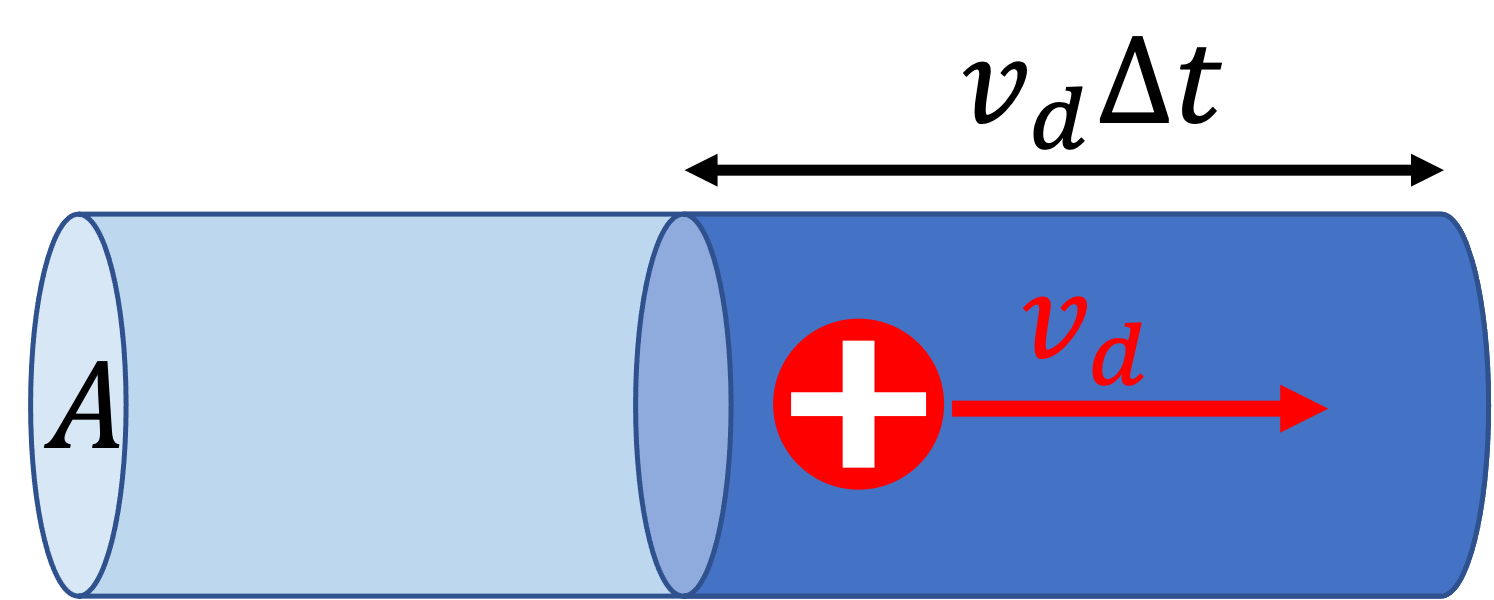
Consider a conductor that has charge carriers traveling to the right at $v_d$ on average as shown in the figure. In time $\Delta t$, the number of charge carriers passing through the right side of the wire is $N = n \times volume = n A v_d \Delta t$. If each charge carriers has charge $q$ (for example, $q=-1.6\times 10^{-19}C$ for an electron), then the total amount of charge carries by all of them is: $$ \begin{eqnarray} \Delta q &=& Nq \\ &=& (n A v_d \Delta t) (q) \\ \Rightarrow \frac{\Delta q}{\Delta t} &=& n q v_d A \\ \Rightarrow I &=& n q v_d A & \text{ because $I= \frac{dq}{dt}$} \end{eqnarray} $$ Not surprisingly, the current $I$ goes up with $v_d$. Note that if the charge carriers are negatively charged, i.e. $q\lt 0$, then $I$ and $v_d$ have the opposite signs, meaning they are in the opposite directions as explained before. One can also write the above equation in terms of the current density as $j = nqv_d$.

Content will be loaded by load_content.js

Current and Potential

Recalls that positive charge flows from high $V$ to low $V$, therefore current always flow from high potential to low potential.

Simulation - Flow of charge in a potential difference

Canvas not supported

Flow of charge in a potential difference

  • Positive charge moves from high $V$ to low $V$.
  • Negative charge moves from low $V$ to high $V$.
    • Potentials $V$ in electricity is like height $h$ in mechanics. An object rolls from high $h$ to low $h$. A positive charge moves from high $V$ to low $V$.
    • Negative charge moves opposite to positive charge. You could imagine if negative mass exists, they will fly into the air instead of falling.

Resistance

The resistance of a conductor is defined to be:

$$ R = \frac{V}{I} \Leftrightarrow V = IR $$

Content will be loaded by load_content.js

Resistivity

The resistance of a conductor depends on the resistivity $\rho$ (unit: $\Omega m$) of the material. For example, copper (a good conductor) has much lower resistivity than glass (an insulator). $\rho$ measures how poorly a material conducts electricity. In addition, we expect the longer the conductor (lenght $l$), the higher the resistance, but a larger cross-sectional area $A$ should lower the resistance (smoother traffic in a wider freeway). In summary:

$$ R = \rho \frac{l}{A} $$
It should be emphasized that $\rho$ depends only on the material, but not on the shape or length of the conductor.

Resistivity of some common materials
Material Resistivity ($\Omega m$)
Silver $1.59\times 10^{-8}$
Copper $1.7\times 10^{-8}$
Gold $2.44\times 10^{-8}$
Aluminum $2.82\times 10^{-8}$
Iron $10\times 10^{-8}$
Lead $22\times 10^{-8}$
Silicon $640$
Glass $10^{12}$
Rubber $10^{13}$

People sometimes use conductivity $\sigma$ , defined as: $$ \sigma = 1/\rho $$ The unit of $\sigma$ is $S/m$, siemens per meter, where $S \equiv \Omega^{-1}$.

Content will be loaded by load_content.js

Power

When a current flows pass a resistor, the power (energy per second) consumed by the resistor is given by:

$$ P = IV = I^2 R $$

Content will be loaded by load_content.js

Non-SI unit of energy: $kWh$ (kilowatt hours)
\(1kWh\) can be thought of as the energy consumed by a \(1kW=1000W\) light bulb in one hour. This definition means we can convert \(1kWh\) back into \(J\) as follows: $$ \begin{eqnarray} 1kWh &=& (1000W)(1h) = (1000J/s)(3600s) \\ &=& 3.6\times 10^6 J \end{eqnarray} $$ The unit is commonly seen on the electricity bill. The current rate is about \($0.35\) per \(kWh\).

Content will be loaded by load_content.js

Resistors in Combination

Resistors in series and in parallel.

Resistors can be used in combinations.

When connected in series:

$$ R_{12} = R_1 + R_2 $$

When connected in parallel:

$$ R_{12} = (R_1^{-1} + R_2^{-1})^{-1} \Leftrightarrow \frac{1}{R_{12}} = \frac{1}{R_1} + \frac{1}{R_2} $$
The equations can be generalized to more resistors.

The equations for combining resistance is exactly opposite to those in combining capacitance. Do not mix them up!

Simulation - Combination of Resistors

Canvas not supported

Combination of Resistors

  • Resistors in series have increased resistance.
  • Resistors in parallel have reduced resistance.
  • For 3 resistors:
    • Series: $R_{123} = R_1 + R_2 + R_3$.
    • Parallel: $R_{123} = (R_1^{-1} + R_2^{-1} + R_3^{-1})^{-1}$.
Content will be loaded by load_content.js

Electromotive Force

Analogy between $V$ and $h$
A battery basically pushes up the electric potential $V$ of a wire so positive charges will flow downstream. It is like elevator that takes balls to a high position (large $h$), and release them to roll down a hill.

The emf of a battery

Internal Resistance

For a non-ideal battery there is a subtle difference between the emf of a battery and the output voltage of a battery due to the presence of the internal resistance $r$. The battery, just like any regular conductors, carries some amount resistance. This internal resistance causes the potential to drop by $I r$ before the current even leaves the battery, therefore the apparent voltage (or the effective voltage) of a battery when measured from the outside is: $$ V_{apparent} = \mathcal{E} - Ir $$

You can play with the simulation below to get a feeling for the effect of the internal resistance. Note that when $I\rightarrow 0$ (such as when the external resistance is very large), then $V_{apparent} \approx \mathcal{E}$.

In this course we will ignore the internal resistance of a battery unless stated otherwise.

Simulation - Internal Resistance

Canvas not supported

Internal Resistance

  • The shaded area represents a non-deal (real) battery with internal resistance $r$.
  • $r$ causes the potential to drop by $Ir$, so the apparent voltage $V_{apparent}$ of the battery is less than the true emf $\mathcal{E}$.
  • The voltmeters above display only the magnitude of the potential difference but not the signs.
  • $V_{apparent}$ is close to $\mathcal{E}$ if $r$ is small compared to $R$. Adjust $r$ and $R$ in the simulation to see.
  • Can you explain why increasing $R$ while keeping $r$ the same increases $V_{apparent}$?
Content will be loaded by load_content.js

Simulation - Electric Potential in a Circuit

Canvas not supported

Electric Potential in a Circuit

  • Battery pushes up the electric potential to $\mathcal{E}$, the emf of the battery (usually just called the voltage of the battery, in the absence of internal resistance).
  • As current flows across a resistor, the electric potential drops by $IR$.

Kirchhoff's Rules

$$ \begin{eqnarray} \sum I_{in} &=& \sum I_{out} \tag{Kirchhoff's junction rule} \\ 0 &=& \sum_{loop} \Delta V \tag{Kirchhoff's loop rule} \end{eqnarray} $$

The junction is often written simply as $\sum I = 0$ with the sign convention introduced below.

Kirchhoff's junction rule

$\sum I_{in} = \sum I_{out}$: Current flowing into and out of a junction, $I_1 + I_2 = I_3 \Rightarrow 1A + 2A = 3A$.
Alternative way to represent the same situation, where $\sum I_{in} = 0$ (there is no $I_{out}$). Negative sign is used to denote when a current is flowing opposite to the arrow. $I_3=-3A$ represents a current leaving the junction because of its negative sign, and we have $I_1 + I_2 + I_3 = 0 \Rightarrow 1A + 2A - 3A = 0A$.

Electric charge is a conserved quantity (as far as we know), meaning the total amount of charge in the universe stays the same, net charges cannot be created nor destroyed. Since current is simply movement of charges, it is not surprising the total current flowing into a junction must equal to the amount going out, i.e. $\sum I_{in} = \sum I_{out}$.

Care must be taken dealing with the signs of the currents, as seen in the figure on the right. We allow negative values when the current is flowing opposite to the arrow in a diagram.

Content will be loaded by load_content.js

Kirchhoff's loop rule

If one follows a wire around a circuit and comes back to the same point, the overall change in the electric potential must be zero, i.e. $\sum_{loop} \Delta V = 0V$.

Analogy: If you follow your change in elevation $\Delta h$ as you go hiking, when you finally return to home, the total sum of all the change in elevation must be zero, i.e. $\sum_{loop} \Delta h = 0m$.

Content will be loaded by load_content.js

Circuit

A circuit is a path for charges to circulate, usually with the aid of a power supply such as a battery.

  • Resistors in series always have the same current.
  • Branches in parallel always have the same total voltage.

Simulation - Circuits with Adjustable Resistance

Canvas not supported

Circuits with Adjustable Resistance

  • Click on a resistor to see details and adjust resistance.
  • Click on the battery to reveal the total current and resistance of the circuit.
  • Observe:
    • Resistors in series always have the same current.
    • Branches in parallel always have the same total voltage.

Simulation - Circuit Step by Step

Canvas not supported

Circuit Step by Step

  1. Resistors in series have increased resistance.
  2. Resistors in parallel have reduced resistance.
  3. For 3 resistors:
    • Series: $R_{123} = R_1 + R_2 + R_3$.
    • Parallel: $R_{123} = (R_1^{-1} + R_2^{-1} + R_3^{-1})^{-1}$.
Content will be loaded by load_content.js

Irreducible circuits

Not every circuit can be solved by the techniques above, combining (i.e. reducing) the resistors until one is left and work backward. Below is an irreducible example, where the presence of multiple batteries block the reduction procedure.

In this case, we apply Kirchhoff's loop rule and junction rule (which are true whether the circuit is reducible or not) to set up multiple equations to find the unknowns.

Content will be loaded by load_content.js

Notations

Name Symbol Unit Meaning
Current $I$ $A$ charges flowing per unit time
Resistance $R$ $\Omega$ hindrance to current
Emf $\mathcal{E}$ $V$ voltage across a battery
Power $P$ $W$ rate of energy consumption
Name Symbol Unit Meaning
Current $I$ $A$ charges flowing per unit time
Current density $j$ $A/m^2$ current per unit area
Drift velocity $v_d$ $m/s$ average velocity of charge carriers
Resistance $R$ $\Omega$ hindrance to current
Resistivity $\rho$ $\Omega m$ how poorly a material conducts electricity
Emf $\mathcal{E}$ $V$ voltage across a battery
Power $P$ $W$ rate of energy consumption