Magnetic field around a magnet. Iron filings (on the left figure) orients themselves along the direction of the magnetic field (shown in the middle figure). The field can also be traced with a compass.
A magnetic field can be produced by a permanent magnet, or a current.
Notation: $\vec B$.
SI unit: $T$ (Tesla).
Earth's magnetic field is about $10^{-4} T$.
$B$ and $E$ are secretly the manifestation of the same thing (the electromagnetic field).
Video - Fun with Ferrofluid
Use this link and this link if you cannot see the videos above.
A ferrofluid is a liquid with some tiny ferromagnetic particles (i.e. tiny magnets) mixed in. The particles try to move according to the magnetic field, but the surface tension of the fluid pulls them back, therefore forming interesting and beautiful patterns.
Simulation - Magnetic Field on Earth (3D)
Magnetic Field on Earth
Notice the geographical north actually carries south magnetic charge and vice versa.
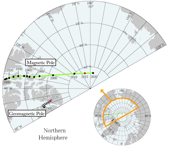
North magnetic pole movement over the years. The "geomagnetic pole" is by computation, while the "magnetic pole" is by direct measurement.
Supercomputer models of Earth's magnetic field. On the left is a normal dipolar magnetic field, typical of the long years between polarity reversals. On the right is the sort of complicated magnetic field Earth has during the upheaval of a reversal.
The short answer is that nobody has ever seen an isolated magnetic charge, called the magnetic monople. You may be tempted to isolate a North magnetic charge by cutting up a magnet and keeping only the $N$ part. However, every cut simply generates more $N$-$S$ pairs.
Fast facts about magnetic monopoles:
Dirac proved that if a single monopole exists somewhere in the universe, then electric charge is quantized. All known free electric charges have discrete values like $0e, \pm 1e, \pm 2e, \cdots$, so it is consistent with (though not a proof of) monopoles' existence.
Most leading theories of particle physics predicts the existence of monopoles and their existence form an integral part of the theories.
Experimental search is ongoing.
While we do not have magnetic monopoles, we do have magnetic dipoles, such as a loop of current which also makes magnetic fields.
Magnetic Force
Here is the equation for the magnetic force on an electric charge $q$ moving at velocity $\vec v$ inside a magnetic field $\vec B$:
$$
\begin{eqnarray}
\vec F &=& q \vec v \times \vec B \tag{vector cross product} \\
F &=& |q v B \sin \phi| \tag{magnitude only}
\end{eqnarray}
$$
The right hand rule for cross product. To get the magnetic force, you still need to multiply $q$ in the end, which flips the vector if $q \lt 0$.
$\phi$ is the angle between $\vec v$ and $\vec B$.
$\vec F \perp \vec v$ and $\vec F \perp \vec B$.
A few special cases:
$v=0 \Rightarrow F = 0$: no motion no force.
$\phi = 0^\circ \text{ or } 180^\circ \Rightarrow F = 0$: no force if $\vec v$ is parallel or anti-parallel to $\vec B$.
$\phi = 90^\circ \Rightarrow \sin \phi = 1 \Rightarrow F = |q v B| $.
The right hand rule for cross product
Index finger: $\vec v$
Middle finger: $\vec B$
Thumb: $\vec v \times \vec B$ (NOT $\vec F$!!!)
Two steps in finding the direction of the magnetic force:
Apply the right hand rule to get $\vec v \times \vec B$ (i.e. your thumb).
Multiply $\vec v \times \vec B$ (thumb) with $q$ to get $\vec F = q (\vec v \times \vec B)$.
If $q\gt 0$, $F$ is in the same direction as your thumb ($\vec v \times \vec B$).
If $q\lt 0$, $F$ is in the opposite direction as your thumb ($\vec v \times \vec B$).
Students often forget to do step 2.
Cross: arrow pointing into the page. Dot: arrow pointing out of the page.
Electric force
Magnetic force
Equation
$\vec F_E = q \vec E$
$\vec F_B = q \vec v \times \vec B$
Velocity dependence
Does not depend on $\vec v$
Depends on $\vec v$
Direction
$\vec F_E$ and $\vec E$ are either parallel or anti-parallel
$\vec F_B$ and $\vec B$ are never parallel, instead $\vec F_B \perp \vec B$
Type
Field and charge are the both electric
Field is magnetic but charge is electric (interaction between magnetic field and magnetic charge will be simpler, but magnetic monopoles have not been seen)
Comparison of electric and magnetic force
Simulation - Magnetic Force on an Electric Charge (3D)
Magnetic Force on an Electric Charge
Use the slider above to adjust the angle of the magnetic field.
Problems involving the magnetic force are inherently 3D, so we will use a cross to denote an arrow going into the page, and a dot to represent an arrow pointing out of the page.
Content will be loaded by load_content.js
Content will be loaded by load_content.js
Content will be loaded by load_content.js
Content will be loaded by load_content.js
Circular Trajectory in Uniform Magnetic Field
Circular trajectory of a charge in a uniform magnetic field.
When an electric charges moves inside a uniform magnetic field:
$\vec F \perp \vec v$, the magnetic force does no work (energy transfer) to the charge.
$W = F s \cos \theta = F s \cos 90^\circ = 0J$.
An electric charge in a magnetic field maintains the same speed.
The charge traces a helical trajectory in general.
If no motion along the direction of the field, then the trajectory is circular.
To work out the radius of the trajectory, recall the equation of centripetal force:
$$
F_{cent} = \frac{mv^2}{r}
$$
The centripetal force is the magnetic force, and the angle $\theta = 90^\circ$ in the case of circular trajectory:
$$
\begin{eqnarray}
F_B &=& |qvB\sin 90^\circ| \\
&=& |q|vB
\end{eqnarray}
$$
Equating the two forces:
$$
\begin{eqnarray}
F_B &=& F_{cent} \\
\Rightarrow |q|vB &=& \frac{mv^2}{r} \\
\Rightarrow r &=& \frac{mv^2}{|q|vB} \\
&=& \frac{mv}{|q|B}
\end{eqnarray}
$$
Simulation - Charge to Mass Ratio with Speed Control
Charge to Mass Ratio with Speed Control
Caution: The number given by the coordinate tool is the diameter of the orbit, not the radius!
$|F_{centripetal}| = m |v|^2/r$
$\vec F_B = q \vec v \times \vec B \Rightarrow |F_B|= |q| |v| |B|$
In practice, it is hard to measure $v$ because small particles travel very fast.
Instead we accelerate particles from rest using a known electric potential $V$ (don't mix up $V$ with $v$!).
$V$ is very easy to measure.
The electric field does work on a charge passing through a potential difference $\Delta V$ given by $W_E = -q \Delta V$.
The work becomes the kinetic energy of the charge: $KE = -q \Delta V$.
Taking absolute value of both sides and writing $V= |\Delta V|$, we can write $KE = |q| V$.
Putting in $KE = \frac{1}{2}m v^2$, we get:
$$
\begin{eqnarray}
\frac{1}{2}m v^2 &=& |q| V \\
\Rightarrow v^2 &=& \frac{2 |q| V}{m}
\end{eqnarray}
$$
Substituting in $F_B = F_{cent}$ like before, but trying to eliminate $v$ in favor of $V$:
$$
\begin{eqnarray}
F_B &=& F_{cent} \\
\Rightarrow |q|vB &=& \frac{mv^2}{r} \\
\Rightarrow |q|B &=& \frac{mv}{r} \\
\Rightarrow |q|^2 B^2 &=& \frac{m^2v^2}{r^2} \\
&=& \frac{m^2(\frac{2 |q| V}{m})}{r^2} \\
\Rightarrow |q|^2 B^2 &=& \frac{2 |q| m V}{r^2} \\
\Rightarrow r = \sqrt{\frac{2 m V}{|q|B^2}}
&\Leftrightarrow& \frac{|q|}{m} = \frac{2 V}{B^2 r^2}
\end{eqnarray}
$$
The last step is written in two ways, depending on whether the charge-to-mass ratio $\frac{|q|}{m}$ is known. If it is, then $r$ could be predicted. In practice, we use measurement of $r$ to deduce the ratio.
Simulation - Charge to Mass Ratio with Electric Potential Control
Charge to Mass Ratio with Electric Potential Control
Caution: The number given by the coordinate tool is the diameter of the orbit, not the radius!
$|F_{centripetal}| = m |v|^2/r$
$\vec F_B = q \vec v \times \vec B \Rightarrow |F_B|= |q| |v| |B|$
When we have electric and magnetic fields crossed with one another, a charge experiences both electric and magnetic force.
$\vec F_E = q \vec E$.
$\vec F_B = q \vec v \times \vec B$.
We can use the case when the two forces cancel out to deduce the velocity of a charged particle.
Assume the two forces point in opposite directions, they cancel out when their magnitudes are the same:
$$
\begin{eqnarray}
F_B &=& F_E \\
|q| v B &=& |q| E \\
v &=& \frac{E}{B}
\end{eqnarray}
$$
So we can find the velocity of a tiny particle by simply taking the ratio of $E$ to $B$ (both are easy to measure) when its trajectory is straight.
Simulation - Crossed Fields
Crossed Fields
Adjust the fields and the velocity to send the charge to the right horizontally (undeflected).
$\vec F_E = q \vec E$, $\vec F_B = q \vec v \times \vec B$
When the charge is undeflected:
$\vec F_E + \vec F_B = \vec 0 \Rightarrow |\vec E| = |\vec v \times \vec B|$.
Content will be loaded by load_content.js
The Hall Effect
Recall that current can be carried by either positive or negative charges. How can we determine the sign of the charges flowing in a particular conductor? The key is to put the conductor in a magnetic field, which pushes the charge carries to one side of the conductor. The simulation below shows how the Hall effect can be observed.
The Hall effect is a phenomenon where a voltage difference, known as the Hall voltage, is generated across a conductor when it carries an electric current and is subjected to a perpendicular magnetic field. This effect occurs because the magnetic field exerts a force on the moving charge carriers (e.g. electrons) within the material, causing them to accumulate on one side of the conductor. This accumulation creates a transverse electric field, leading to a steady-state Hall voltage. The Hall effect is widely used to measure magnetic field strength, determine the type of charge carriers in a material, and calculate carrier density and mobility. It is also the principle behind Hall effect sensors, commonly used in various devices for position, speed, and current sensing.
Simulation - The Hall Effect
Hall Effect
The simulation shows a currrent flowing toward you. It can be represented by positive charge carriers with velocity pointing toward you, or negative charge carriers with velocity pointing away from you.
Because $\vec F_B = q \vec v \times \vec B = (-q) (-\vec v) \times \vec B$, magnetic force does not change if you flip the signs of both $q$ and $\vec v$.
Click on "Toggle Charge Carriers" to see that the charge carriers are pushed to the left no matter the sign of the charge.
If the charge carriers are positive, their concentration on the left will generate a high electric potential on the left side.
If the charge carriers are negative, their concentration on the left will generate a low electric potential on the left side.
The potential difference, called the Hall voltage can be measured by a voltmeter connected across both sides of the conductor.
Magnetic Force on a Current
Since current is a collection of charges in motion, when it is placed inside a magnetic field, a magnetic force results:
$$
\begin{eqnarray}
\vec F &=& I \vec L \times \vec B \tag{vector cross product} \\
F &=& |I L B \sin \phi| \tag{magnitude only}
\end{eqnarray}
$$
$\vec L$ is the length of the wire, pointing in the direction of the current.
Physicists like to use $I$ as just the magnitude, so we give the direction of the current to $\vec L$ instead.
$\phi$ is the angle between the current and the magnetic field.
The same cross product before applies.
It is not a new force, fundamentally the same as $\vec F = q \vec v \times \vec B$, but applied to a large number of charges moving in a wire.
Simulation - Magnetic Force on Current (3D)
Magnetic Force on Current
Use the slider above to adjust the angle of the magnetic field.
Content will be loaded by load_content.js
Content will be loaded by load_content.js
Content will be loaded by load_content.js
Magnetic Moment
The right hand grip rule. The four fingers curve in the direction of the current, the thumb gives the direction of the area vector $\vec A$.
SVGguru, CC BY-SA 4.0 , via Wikimedia Commons
The area vector
Consider a loop of wire carrying a current $I$. We define the area vector $\vec A$ to have a magnitude equal to the area enclosed by the loop, and points perpendicularly to the area enclosed by the current (similar to the area vector defined with Gauss' law). Since there are two vectors perpendicular each planar surface, we use the right hand grip rule to settle the ambiguity (see figure). Your four fingers wraps around the direction of the current, the thumb gives the direction of $\vec A$.
Magnetic dipole moment
The magnetic dipole moment of a loop of current is defined to be:
$$
\vec \mu = I \vec A
$$
It can be shown in the example below the torque on current loop due to an magnetic field is $\vec \tau = \vec \mu \times \vec B$.
Content will be loaded by load_content.js
Notations
Name
Symbol
Unit
Meaning
Magnetic field
$\vec B$
$T$
Field produced by magnets or currents
Magnetic force
$F_B$
$N$
Force produced by magnetic field on charges or currents. $\vec F_B = q\vec v \times \vec B$, $\vec F_B = I \vec L \times \vec B$.


