Lenses
Lenses are designed to refract light in a specific way to form images.
-
Terminology:
- Principle axis: the axis that passes through the center of the lens.
- $F$: focal point, where rays parallel to the principle axis meet.
- $2F$: a point twice as far from the lens as the focal point.
- $f$: focal length, the distance between $F$ and the lens.
- $p$: object distance, the distance between the object and the lens.
- $i$: image distance, the distance between the image and the lens.
- The idea of a focal point is actually an naive idealization.
- In theory and in reality, one cannot construct a static lens or mirror that gathers all parallel light rays to an arbitrarily small point.
- It would have violated the second law of thermodynamics because such a lens could generate an arbitrarily high temperature from a low temperature light source.
- Mathematically it came from the conservation of volume in phase space $\Delta x \Delta p$ in classical mechanics.
- Light rays will always miss each other slighlty around the focal point (i.e. slightly blurring the image) due to the above fundamental constraint from physics.
There are two types of lenses:
-
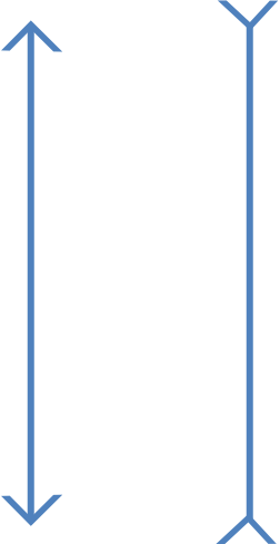
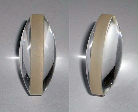
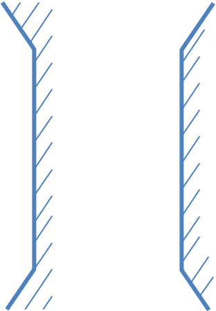
Coverging lens
- Also known as convex lens or positive lens.
- Thicker in the middle, thinner on the edge.
- Focal length $f$ is always positive.
-
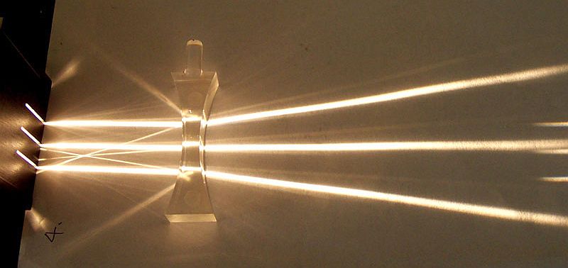
Diverging lens
- Also known as concave lens or negative lens.
- Thinner in the middle, thicker on the edge.
- Focal length $f$ is always negative.


Principle rays
- There are 3 principle rays: simple rays that are used to find the image.
- Click on the Switch Rays button below to see the rules for the principle rays.
- Drag the focal point to the other side to change to a diverging lens.
Simulation - Converging and Diverging Lens: The Principle Rays
Dragging the focal points to the other side of the lens will change the lens from converging to diverging and vice versa.
Click on "Switch Rays" to show one principle ray at a time.
This simulation focuses on showing the rules regarding the principle rays so the image is purposely omitted. See the next simulation to learn how to find the image.

Image formation
- Image is located where the rays meet.
- If the rays diverge on the right, then trace the rays backward. The meeting point of the extrapolated rays is the location of the image.
Real vs virtual image
- Real image is an image that can be projected onto a screen without additional lenses or mirrors.
- Virtual image is an image that cannot be projected onto a screen without additional lenses or mirrors.
- Real image is formed when rays converge at a location.
- Virtual image is formed when rays diverge, but can be extrapolated backward to a meeting point.
- In the case of a single lens, real image is always on the right of the lens, and virtual image is always left of the lens. This is not true for multiple lenses.
Drawing ray diagrams
- Draw the ray diagram in 1:1 scale unless you are specifically asked to do otherwise or if the dimensions are clearly too big to fit on a single page.
- Use a pencil as opposed to a ball pen so you can erase and perfect your drawing.
- Use rulers for every single line.
- Light rays should have arrows on them to indicate their directions.
- Always mark and label the focal points.
- Measure and indicate the image distance on your diagram.
- Two rays are sufficient to identify the location of the image. The third principle ray can be used to double check, or you can use the lens equation (see below) to confirm.
- For curved mirrors (in later section) you will need a protractor for one of the principle rays.
- One ray diagram per page so you have plenty of space.
- Practice, practice, practice!
Simulation - Converging and Diverging Lens: Finding the Image
Dragging the focal points to the other side of the lens will change the lens from converging to diverging and vice versa.
Video - Ray diagrams for lenses 1
Use this link if you cannot see the video above.
Video - Ray diagrams for lenses 02
Use this link if you cannot see the video above.
The lens equation
The location of the image can be found using the lens equation:
Lateral magnification
The magnification is the ratio of the image size $h_i$ to the object size $h_o$, and can be found with the object and image distances:- When $m \lt 0$, the image is inverted and $h_i \lt 0$.
- When $|m| \lt 1$, the image is diminished.
- When $|m| \gt 1$, the image is magnified.
Describing the image
If you are asked to describe the image, it means answering three questions:- Is the image upright or inverted?
- Is the image magnified or diminished?
- Is the image real or virtual?
- Upright.
- Diminished.
- Virtual.
When the object is on the focal point of a converging lens (i.e. $p=f$, the case between the two exercises above), the outgoing light rays are parallel and therefore never meet. We either say "no image is formed", or "the image is at infinity".


Simulation - Two Lenses
Dragging the focal points to the other side of the lens will change the lens from converging to diverging and vice versa.


