Section Physical Optics (Diffraction and Diffraction Grating)

Contents here are to be loaded by web lectures

Diffraction

Laser Interference
Diffraction pattern of a red laser beam after passing through a small circular aperture.
Wave Diffraction 4Lambda Slit
A wave passing through a single slit with a width $a \approx 4 \lambda$.
Single slit and double slit2
Fringes produced from a single-slit and a double-slit. Since each of the double slits has a finite width, the double-slit also exibits the single-slit pattern in the background. Technically, the double-slit pattern is the combination ("convolution") of the single-slit pattern and the evenly-spaced double-slit pattern (for infinitely narrow slits).

What is diffraction?

For a single-slit of width $a$, destructive interference occurs at the angle give by:

$$ a \sin\theta_m = m \lambda \hspace{1cm} \text{($m$-th minima)} $$
where $m$ is an non-zero integer.

Compare with the double-slit inteference side by side:

$$ d \sin\theta_m = m \lambda \hspace{1cm} \text{($m$-th maxima)} $$
where $m$ is any integer, including zero.

Comparison of two equations.
Single-slit Double-slit
$a \sin\theta_m = m \lambda$ $d \sin\theta_m = m \lambda$
$a$: width of the slit $d$: separation between two slits
minima for integer $m\neq 0$ maxima for integer $m$
$m=0$ gives the central maximum. $m=0$ gives the central maximum.
central maximum twice as wide as other maxima central maximum is approximately the same width as other maxima
central maximum much brighter than other maxima central maximum is roughly the same brightness as other maxima (for very narrow slits)

Simulation - Single Slit Diffraction

Canvas not supported

Single-Slit Diffraction

A lab manual based on this simulation is available here.

Drag on the barriers to change slit width. Drag the screen and the circle to change their positions. The phasor diagram can also be moved by dragging on the lime-colored dot.
Red/blue are used to represent long/short wavelength for illustrative purpose only. The numerical values of the wavelength in this simulation do not in fact match with the actual wavelength of visible light.

Calculations will appear here.
Content will be loaded by load_content.js
Position of the $m$-th order dark fringe, $y_m = L \tan \theta_m$.

Location of the dark fringes
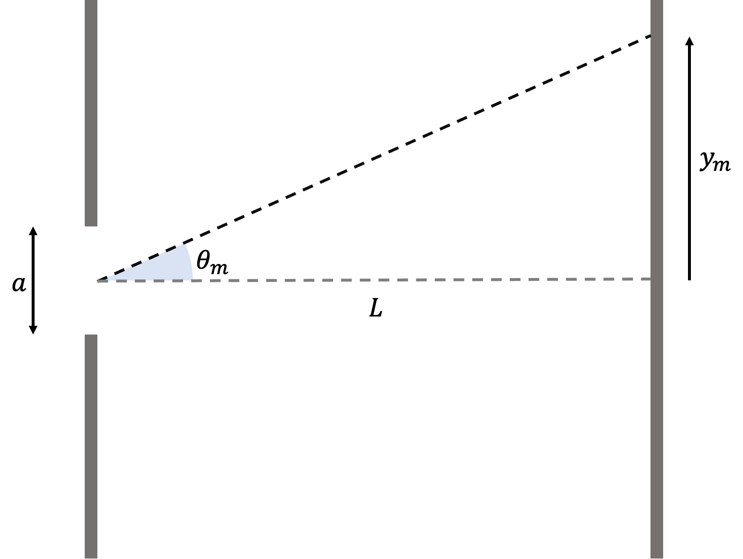
Simple trigonometry tells us the vertical position of the $m$-th order dark fringe is: $$ \begin{eqnarray} \tan \theta_m &=& \frac{y_m}{L} \\ \Rightarrow y_m &=& L \tan \theta_m \end{eqnarray} $$ where $L$ is the separation between the viewing screen and the slit.

Applying the small angle approximation, we have: $$ \begin{eqnarray} y_m &=& L \tan \theta_m \approx L \sin \theta_m \tag{*} \end{eqnarray} $$

But we know the $m$-order minimum obeys: $$ \begin{eqnarray} a\sin\theta_m &=& m\lambda \\ \Rightarrow \sin \theta_m &=& m \frac{\lambda}{a} \end{eqnarray} $$ Put this into (*) gives: $$ \begin{eqnarray} y_m &\approx& L \sin \theta_m \\ &=& L (m \frac{\lambda}{a}) \\ \Rightarrow y_m &\approx& m \frac{\lambda}{a} L \end{eqnarray} $$ Remember $m\neq 0$ for the minima.

For single-slit, because the central maximum is so much brighter than all other maxima, we usually only care about the central maximum. The dark fringes on both sides of the central maximum is $m=\pm 1$: $$ \begin{eqnarray} \theta_1 &\approx& \sin \theta_1 = \frac{\lambda}{a} \\ y_1 &\approx& \frac{\lambda}{a} L \end{eqnarray} $$

The width $w$ of the central maximum is twice that of $y_1$: $$ w = 2 y_1 = 2\frac{\lambda}{a} L $$

$y_m$ without small angle approximation

For waves of long wavelengths, such as sound, radio waves, microwaves, one should not use the small angle approximation (because of large angle $\theta$). In this case, the minima are at ($m\neq 0$): $$ \begin{eqnarray} a\sin\theta_m &=& m\lambda \\ \Rightarrow \theta_m &=& \sin^{-1} (m \frac{\lambda}{a}) \end{eqnarray} $$ Putting into $y_m = L \tan \theta_m$ gives: $$ y_m = L \tan (\sin^{-1} (m \frac{\lambda}{a})) $$ Most of the problems in this course are for visible light, so it is usually safe to make the small angle approximation.

Content will be loaded by load_content.js

Resolvability

Since the first minimum is at angle $\theta_1 \approx \frac{\lambda}{a}$, Rayleigh's criterion requires the angular separation $\theta$ to obey:

$$ \theta \geq \frac{\lambda}{a} $$

For a circular aperture (as opposed to a slit), the minimum angle is modified by a factor to $\theta_1 \approx 1.22 \frac{\lambda}{a}$, hence:

$$ \theta \geq 1.22 \frac{\lambda}{a} $$
We often write the minimum angle on the right hand side as $\theta_R = 1.22 \frac{\lambda}{a}$.

Simulation - Rayleigh's Criterion

Canvas not supported

Rayleigh's Criterion

A lab manual based on this simulation is available here.

Drag on the barriers to change slit width. Drag the screen and the circles (light sources) to change their positions.

Calculations will appear here.
Content will be loaded by load_content.js

Diffraction Grating

Locations of the maxima of a diffraction grating is the same as the double-slit, given by:

$$ d \sin\theta = m\lambda $$
where $d$ is the separation between neighboring slits.

$d$ for diffration gratings could be made very small, giving relatively large value of $\theta$ ($\theta \sim 1rad$). Therefore it is better not to use the small angle approximations.

Simulation - Multiple Slits Interference

Canvas not supported

Multi-Slit Diffraction

Drag the screen and the circle to change their positions. The phasor diagram can also be moved by dragging on the lime-colored dot.
Red/blue are used to represent long/short wavelength for illustrative purpose only. The numerical values of the wavelength in this simulation do not in fact match with the actual wavelength of visible light.
The intensity graph is normalized so the peak intensity is always the same (in reality, as the number of slits increases, the peak intensity increases as well).
Calculations will appear here.
Diffraction2vs5
Fringes produced on a screen by multiple slits. The upper fringes are produced with less slits than the lower fringes.
Diffraction-red laser-diffraction grating PNr°0126
Diffraction of a red Laser beam with a diffraction grating.

Simulation - Two Colors in Multi-slit Interference

Canvas not supported

Diffraction with Two Wavelengths

Illustrate how diffraction gratings (with a large number of slits) is useful in distinguishing different wavelengths. Decrease the number of slits and see how the fringes of the two sources get all mixed up and difficult to distinguish from one another.
Control: Drag the screen to change its position.
Red/blue are used to represent long/short wavelength for illustrative purpose only. The numerical values of the wavelength in this simulation do not in fact match with the actual wavelength of visible light.
The intensity graph is normalized so the peak intensity is always the same (in reality, as the number of slits increases, the peak intensity increases as well).
Calculations will appear here.
Content will be loaded by load_content.js